Diesel Jeep Liberty KJ Timing Belt Replacement Guide:
This is a "how-to" timing belt replacement guide intended to be used by various skill level owners/mechanics. I will explain the options for the service, options for parts, and what I think is the best way to proceed with the service. Please note this is only a guide and not a guarantee that you won't mess something up. If you don't feel comfortable doing the service take it to someone else, don't blame me if you mess something up! There I said it!
Let's start off with the parts you will need:
The prices shown reflect MSRP as of 6/29/11, generally online parts retailers offer them at 20-25% below list price
Timing Belt ...................5142579AA - $209
Tensioner Pulley ..............5142798AA - $126
Idler pulley (2 required) .....5142573AA - $62.75
Timing cover gasket ...........5066921AA - $18.75
Water pump ....................5142985AA - $267
Water pump O ring .............5159019AA - $6.25
Water pump gasket ...............4864575 - $3.60
Thermostat ....................5142601AA - $146
Thermostat gasket .............5066806AA - $2.85
Other:
Zerex G-05 coolant, about 1.3 gallons lost during the procedure. Serpentine belt. Serpentine belt tensioner. Fan clutch. Alternator/decoupler. JB weld(for intercooler leaks).
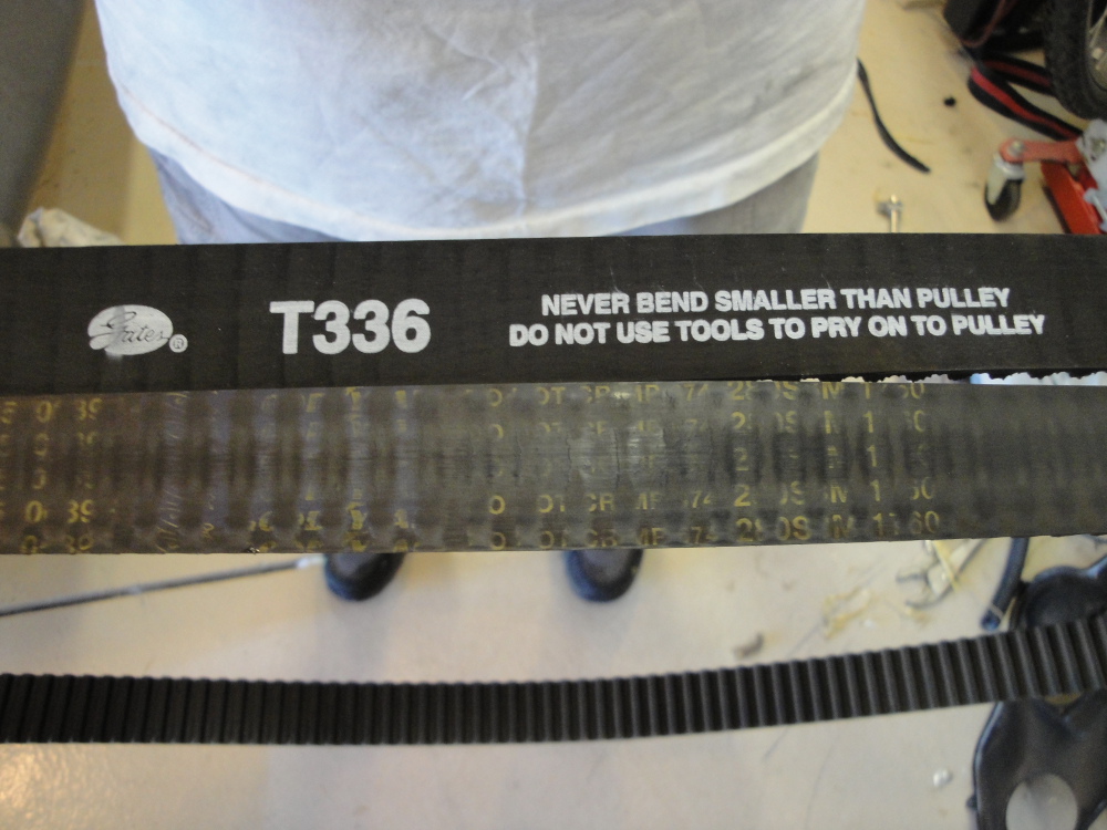
There are aftermarket alternatives available. Gates has a good quality timing belt that will cost you about $85 online. Crown auto makes a timing belt tensioner and idlers. Amazon and Rockauto both have the gates timing belt. IDparts.com also now carries various parts for the CRD including a kit for the timing belt service:
http://www.idparts.com/catalog/
There have been TWO reported failures of a crown water pump shortly after install, one of which had a slipped belt that then did internal damage to the engine, specifically the rockers. (The rockers are designed to fail instead of the valves bending, but replacing the rockers typically runs about $800 for the parts alone) There has been another reported machining defect of a crown pump where it would not bolt to the block.
The crown pump costs about $115 online from, the OEM pump costs about $200 online or with a shop discount(prices reflect April of 2012).
Please see this thread for details on the crown water pump failure:
http://www.lostjeeps.com/forum/phpBB3/viewtopic.php?f=5&t=66469
There are three levels of service for the 100k timing belt, each one will replace the most critical component, the timing belt, but if you are strapped for cash a cheaper service is more important than waiting. If you do the labor yourself and only replace the timing belt you can get away with the replacement for ~$100. If your belt slips or breaks its a minimum of $800 in new rockers.....plus all the other costs you are going to incur. You should not put off doing the belt over a matter of a few hundred dollars. It is better to only replace the belt than to do nothing at all!
That being said, here are the three levels of service you can do, and anything in between, that reflect different levels of cost.
- Level One: Timing belt only
- Level Two: Timing belt, idlers, tensioner, misc
- Level Three: Timing belt, idlers, tensioner, water pump, misc
-
Level One is the cheapest, if you are strapped for cash and just need to get the belt done there is no shame in doing just the belt, people have rolled the dice and held off on doing the belt and then later regretted it. Even a full Level Three service is cheaper than a broken or slipped belt.
- Level Two is a reasonable service for 100k, if you do a level Two service at 100k I would recommend a Level Three service at 200k. The level two service I leave up to the customer to decide, generally I recommend a level Two service at the minimum if you are paying someone to do the service. If you are doing it yourself and have the ability to dig back into the Jeep anytime in the future you may wish to save yourself a little money and not do the water pump at this point, but instead do the water pump at 200k. Just note that the water pump replacement(Level Three) is about an hours more worth of work than just the timing belt(Level Two).
- Level Three is probably the "best" in terms of a full service, but will also cost the most. If you are paying someone to do the job I would recommend spending the extra $200 online for an OEM water pump. You will pay more in labor for the whole job than you will for the OEM water pump, if your coolant has never been changed, or is questionable, its somewhat more likely that you will have water pump trouble. Of course this is not always the case, I had a customer that had taken meticulous care of his CRD, regular coolant changes, not abused, etc, he decided not to do the water pump at the time we did his belt. About 5k miles after the belt change his water pump started leaking. The same week his water pump started leaking another owner reported that his brand new Crown brand water pump which had just been installed also started leaking. Therefor based off of those two cases I think the best option is to replace the pump with a new OEM unit ordered online ~$200. I would like to note that on my personal vehicle and several others I have not replaced the water pump and they are just fine, point being, it can be hit or miss, but the best case is probably to replace the pump with an OEM unit. Generally I leave this decision up to the customer, but discuss the merits of each approach with them.
Misc items: There are also some misc things that you may wish to do while performing the service, there are replacement dust seals for the rear TB cover, I don't think these are necessary at all. If this concerns you its far cheaper just to use a little RTV on the rear cover before installing it back onto the block.
The serpentine tensioner can sometimes go bad, if your alternator decoupler is failing. If the tensioner is on its way out I would recommend you replace during the TB service, it has to come off anyway so its a good time to toss on a new one.
Likewise if your serpentine belt is older it has to come off anyway so its a good time to throw on a new one, and it will never be easier. If your alternator decoupler is on its way out this is also a good time to replace it. The alternator needs to come off to install the intake cam locking pin, so its very easy to install a new one then(autozone has a reasonably priced rebuilt alternator that comes with a new decoupler).
This is also an excellent time to replace your mechanical fan clutch with a new one. At 100k my cooling fan clutch just wasn't working like it should, I was driving up hills on the interstate in moderately warm weather where my temperature would climb steadily to the 3/4 mark where in years past it had not done that. Replacing the fan clutch solved that problem. Plus, its off already so its easy to install a new one.
If your thermostat is questionable or has never been replaced this may be a good time to do that as well. Many OEM thermostats have failed before 100k, making the vehicle take forever to warm up or it never reaching full operating temp.....which can kill your fuel economy.
A note on coolant: You will loose about 1-1.5 gallons during the procedure. Buy one gallon, add it, and make the second fillup all water(something like a 70/30 mix), or buy two gallons and all coolant and keep a little extra around. I like this option more, if you ever need to add coolant in the future you can just add the rest of the coolant you have, and then later add water up to two gallons without worrying about keeping adequate freeze and corrosion protection.
Overall procedure:
These are the basic steps to follow, I will discuss the details below.
1. Remove stuff in the way(fan shroud, radiator, whatever it takes)
2. Remove mechanical Fan.
3. Remove Serpentine Belt.
4. Remove Mechanical Fan pulley/mount.
5. Remove Serpentine Belt Auto tensioner.
6. Remove crank pulley.
7. Remove front cover.
8. Install cam lock pins/crank lock pin/cam locking tool.
9. Add alignment marks on the crank, injection pump, and cam gears for safeties sake and to insure the CP3 injection pump stays timed correctly.
10. Loosen TB belt pulley tensioner bolt.
11. Use tensioner tool to back the tension off of the belt.
12. Remove Belt.
13: skip if not doing water pump
13a. Remove cam gears
Only do this with cam locking pins installed and gear holder in place. The torque required for the cam gear bolts can break the locking pins!)
13b. Remove rear cover.
13c. Remove viscous heater.
13d. Remove water pump front half.
13e. Install water pump front half.
13f. Install viscous heater.
13g. Install rear cover.
13h. Install cam gears
Only do this with the cam locking pins installed and gear holder in place. The torque required for the cam gear bolts can break the locking pins!
14. Install new belt.
15. Reverse of removal.
The design of the fan shroud, fan clutch, and AC lines makes this job just all a bit harder to do, but not impossible. In general this is the breakdown of how I do it.
Front end assembly removal procedure:
1. Remove grill.
2. Remove bumper.
3. Remove header panel.
4. Remove upper radiator support.
5. Remove electric cooling fan.
6. Remove all bolts holding the AC condenser to the intercooler. The intercooler to the body, and the fan shroud to the radiator.
7. Remove fan shroud: Pull radiator, intercooler, and AC condenser forward, slip fan shroud up(this is kinda tight and hard to do, so it will take some practice to get things to goto the right place and slide out. )
8. Remove intercooler(also a bit tricky).
9. Remove radiator.
10. Remove fan clutch.
11. Remove Serpentine belt, fan idler, crank pulley, PS pump pulley, and serpentine belt tensioner.
12. Proceed with timing belt job.
Now that being said here is the nitty gritty, the stuff you need to know to get it done, the above steps make it seem pretty easy, but its not, and the devil is in the details, its the little tips and tricks that make it easy or hard. Skip down a little bit if your already torn down to the point of the timing belt, the first part of this document deals with how to get the front end apart so you can get to the timing belt.
(Note: pictures for this section are not yet complete)
1. Remove Grill:
The grill comes off very easy, along the top of the grill there are plastic clips that hold it to the header panel, pull up and then forward on them and you will see it start to come off. Work your way along the grill until all of them and off and it will just pull out.
2. Remove bumper.
With the grill off you will see two 10mm bolts, one on each side by the turn signal. Remove them. Go underneath and look for two 10mm bolts pointed vertically that attach to the lower radiator support, remove them. There is a plastic push retainer that holds the front bumper to the plastic splash shield on the right and left splash shields, remove it from below. In each fenderwell there are two plastic reusable rivets that hold the splash shield to the bumper cover. Pull out on the center post then you can pull the whole fastener out, save all these parts for reuse. There is a plastic tab that goes from the fender flare to the bumper cover, you will just have to play with this to get it to come out while you remove the bumper cover. With the bumper cover dropped down there will be two wiring plugs to disconnect for the light attached to the body. Slide the red tab back and then push down on the retainer, the plug will then pull apart. Set bumper assembly aside.
3. Remove header panel.
There will be three 10 mm bolts on either side of the radiator support by the fender, remove all of these. Remove the plastic fasteners holding the plastic air shields to the header panel. The header panel will now come forward, complete with lights attached. By the drivers side fender you will see the headlight harness plug, slide the red tab over and then squeeze the plastic clip, it will then pull apart. Set complete header panels aside.
4. Remove upper radiator support.
In step 3 you removed 4 of the bolts that hold the upper radiator support in place, remove the last two 10mm bolts located on the bumper support in the center just in front of the electric fan. Pull the radiator support off paying attention to the washer bottle cap sliding off of the fill neck. Let the radiator support dangle out of the way down by the drivers front tire.
5. Remove electric cooling fan.
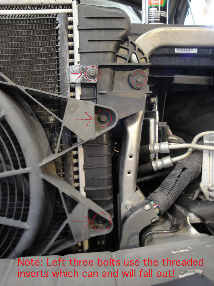
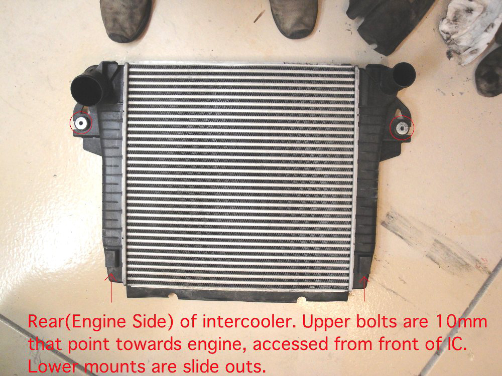
Here you can see the two bolts holding the electric cooling fan to the intercooler on the drivers side. Remove them. Remove the two upper bolts also circled.
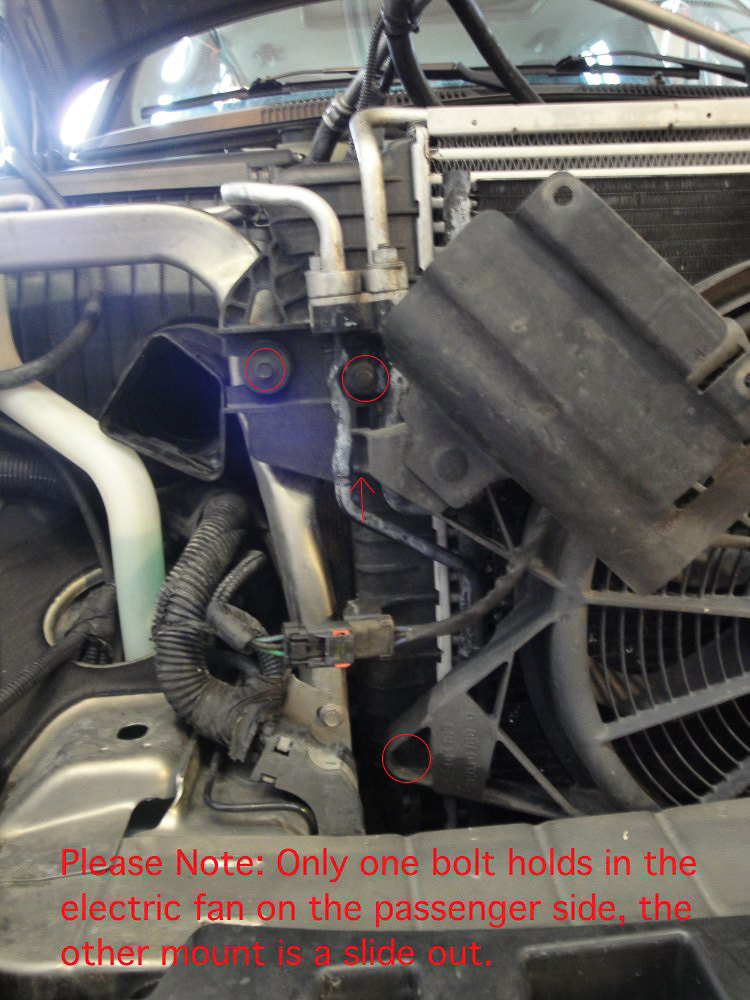
Here you can see the single bolt on the passenger side, remove it and the slide the fan upward. Disconnect the electric plug, slide the red tab over and squeeze the retainer, pull apart. Set the fan aside. Remove the two upper bolts also circled.
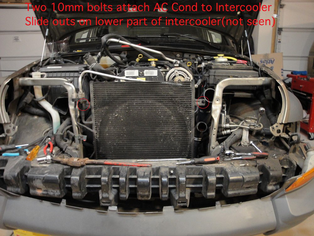
6. Remove all bolts holding the AC condenser to the intercooler
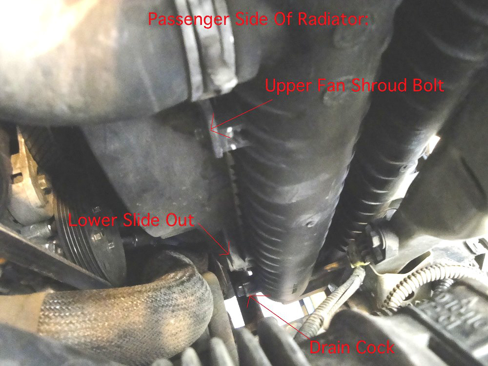
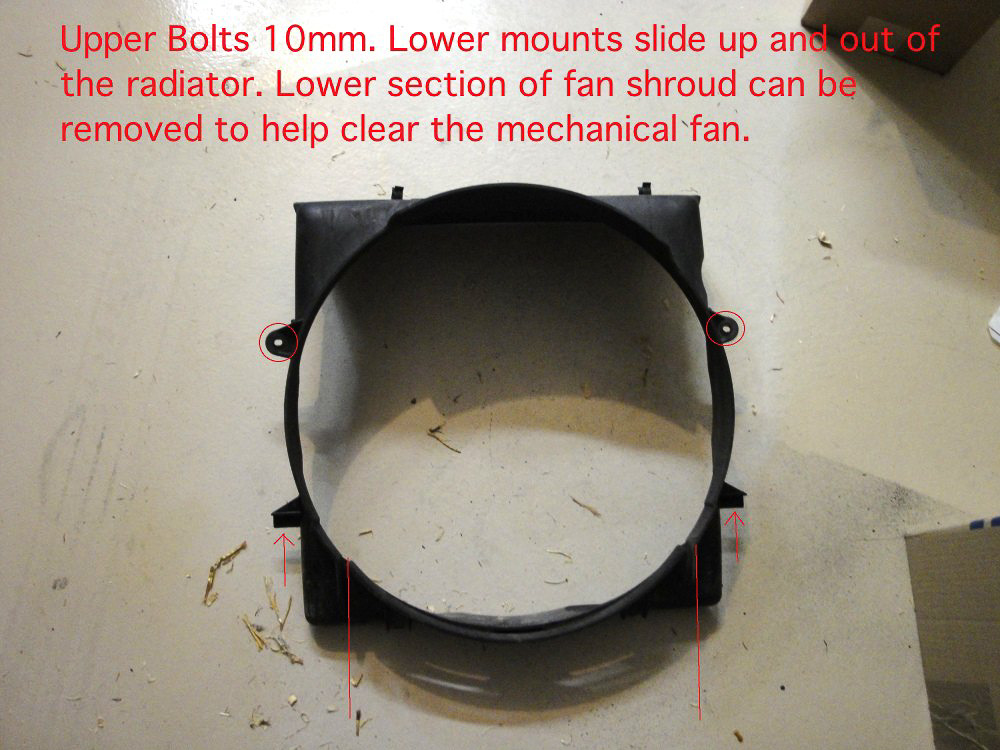
If you have not removed all of the circled bolts in the step above do so now. Remove the upper fan shroud bolts, 1 10mm on each side.

There are two bolts that hold the IC to the radiator on the top, here you can see one of them on the far left of the image. There is another on the drivers side in the analogous location, remove them.
7. Remove fan shroud:
Pull the ac condenser up and then forward, then pull the radiator forward, if you have not done so yet remove the upper radiator hose. With the radiator/IC/condenser pulled forward carefully pull the fan shroud out. It's tight but it can be done.
8. Remove intercooler
The intercooler will slide up and then come up. It will take some work to clear both the radiator and condenser, I often end up rotating the AC condenser counter clockwise pivoting at about the inlet until it is nearly upside down, and then pulling the inlet tube out, you can figure out what works for you. Be careful that the metal square nuts don't fall out of the intercooler or radiator while removing.
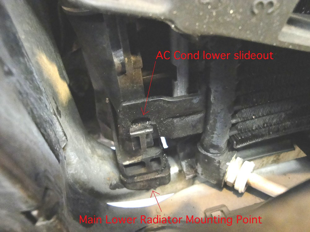
9. Remove radiator
Put a bucket under the drain cock and then open it, go get lunch or a snack while you let it drain. Remove lower radiator hose, pull the radiator out.
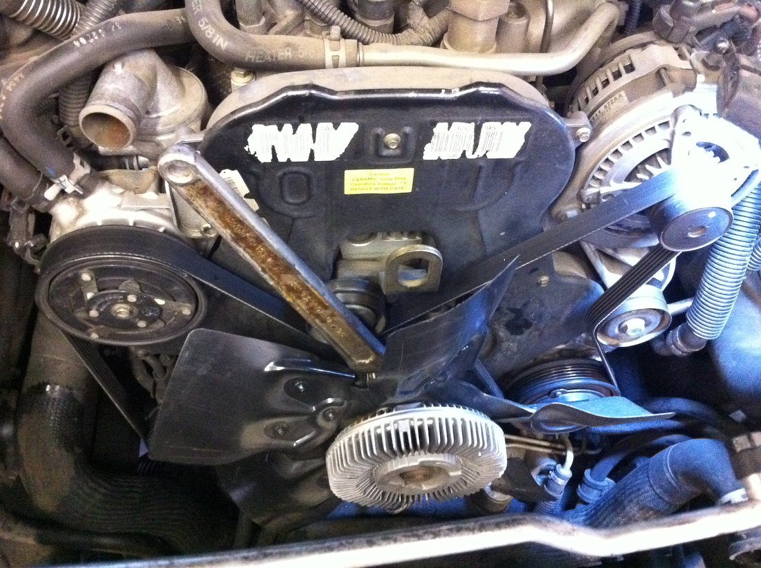
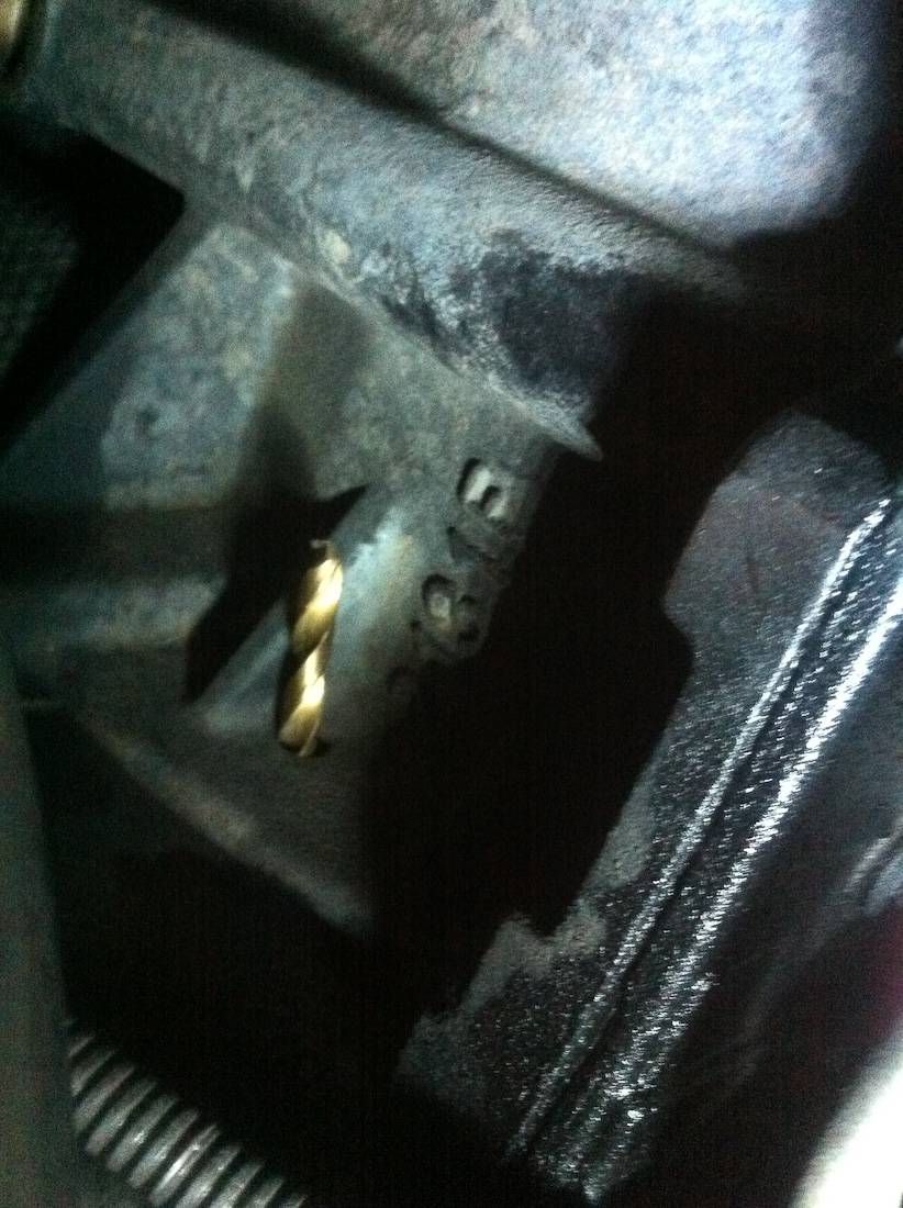
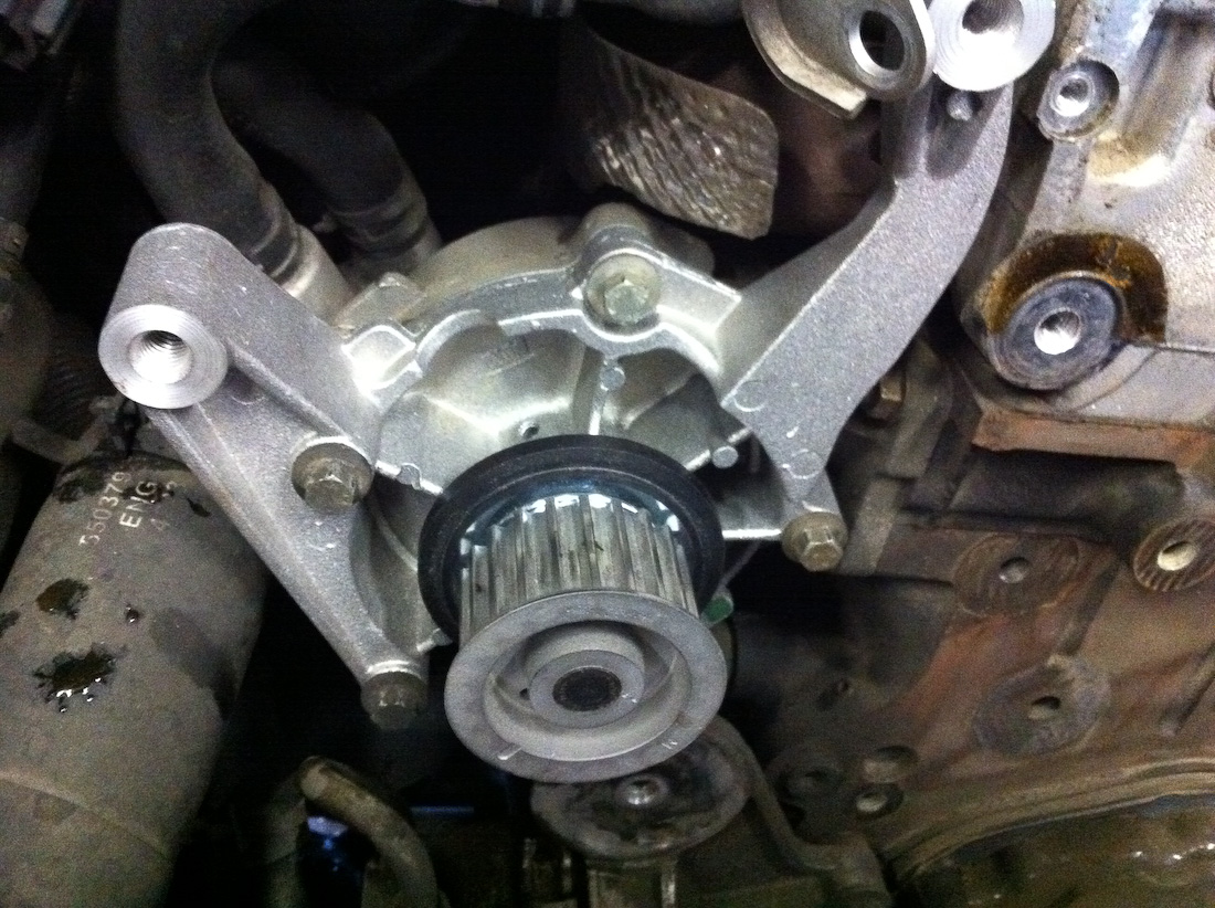
10. Remove fan clutch.
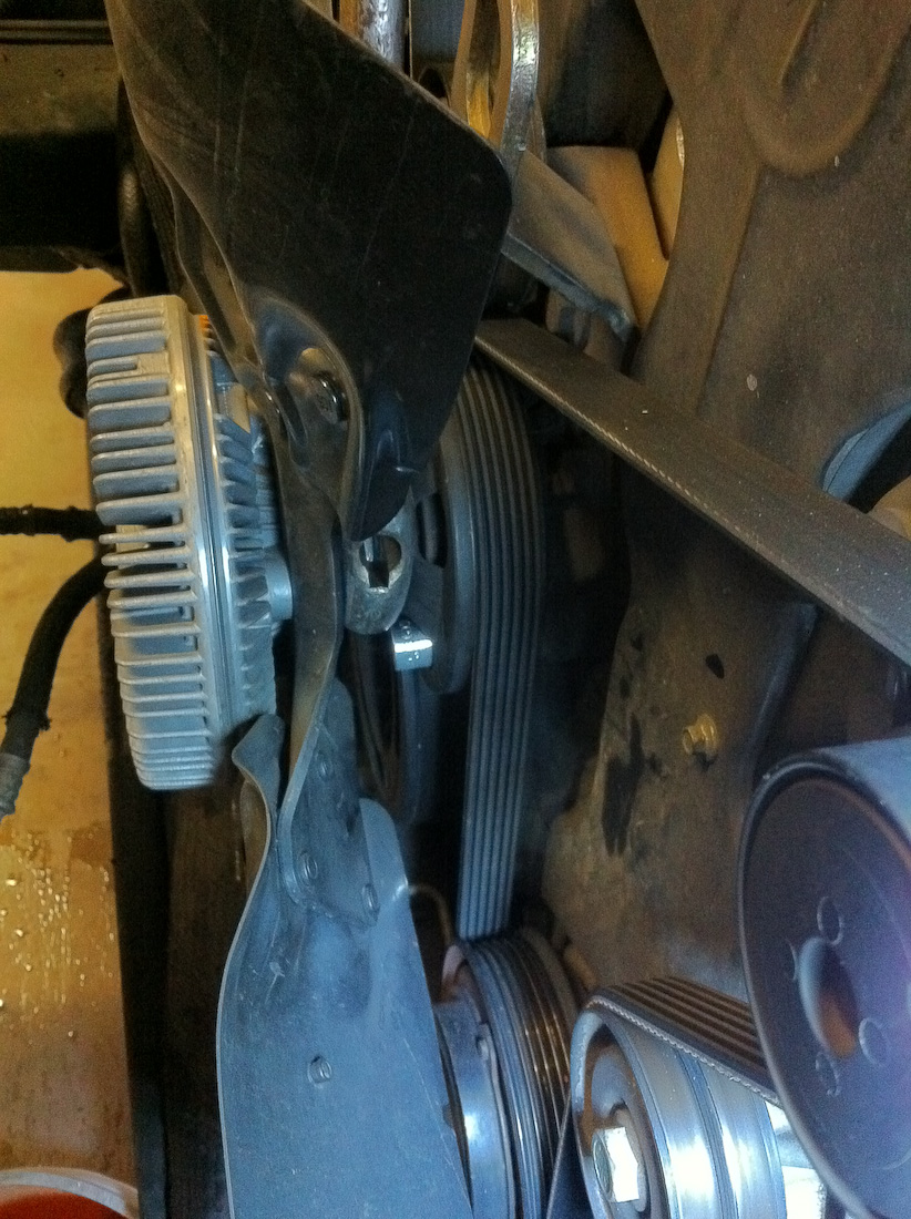
This is the fun part, but now with all this stuff out of the way its not too hard. To remove it you will need a large cresent wrench, or the correct size wrench(I think it might be 36mm but don't quote me on that). Take a 13mm shallow socket(6 point preferable) and place in on one of the bolts that holds the fan idler to the block. This photo illustrates where you want to place the socket:
With one finger hold the socket in place, and with your other hand operate the wrench to get the fan nut off, it may be very tight. The point of the socket is to keep the pulley from spinning.
11. Remove Serpentine belt, fan idler, crank pulley, PS pump pulley, and serpentine belt tensioner.
First take the tension off of the belt, I use a 15mm wrench to apply leverage and remove the tension, then with the tension off I slip the belt off of the idler below the alternator, then I pull the belt off at the alternator, then I can release tension, remove the belt and set the belt aside.
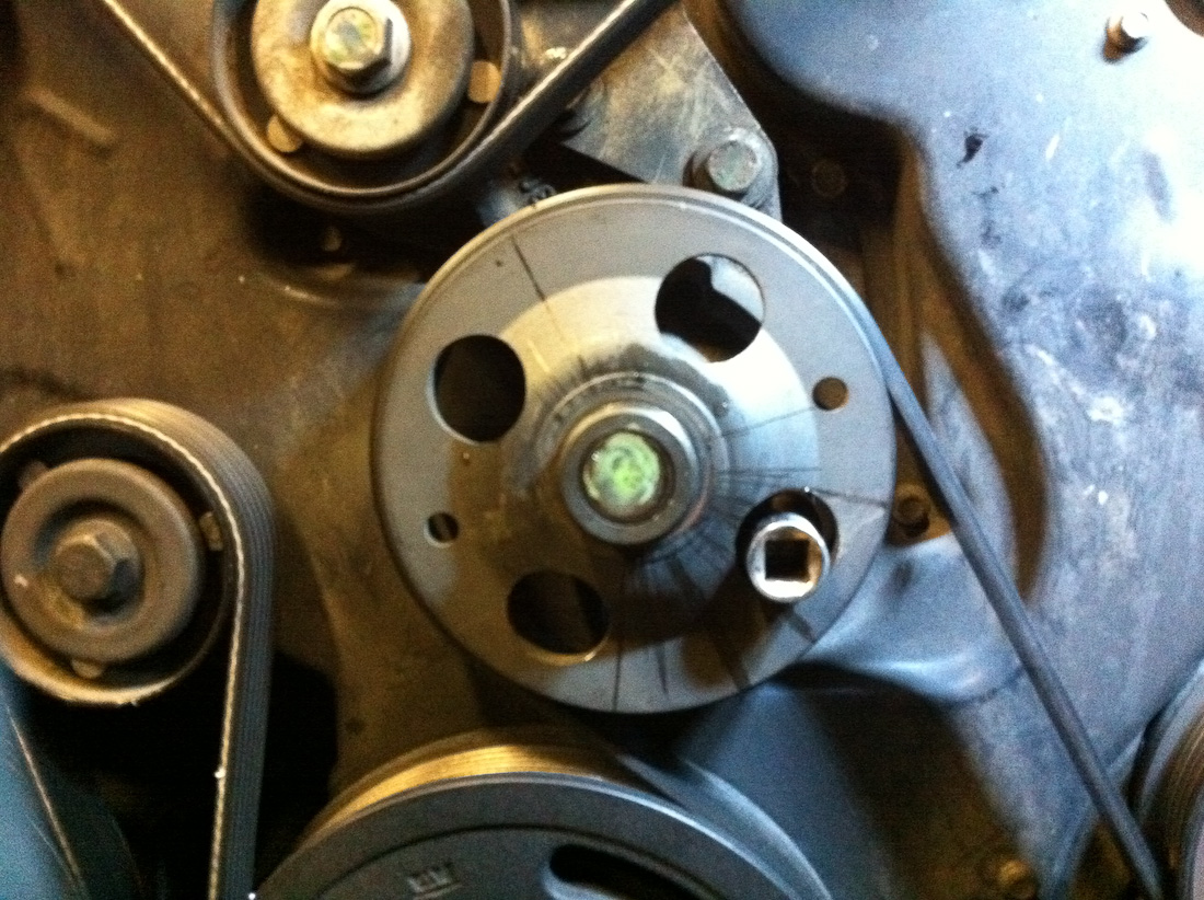
Remove both serpentine belt idlers, they are both reverse thread, turn Clockwise to loosen! Set aside. Remove the fan idler, you will need to use the access hole to get to the bolt you put the socket on in the above step, set the fan idler aside. Remove the PS pulley(3x10mm bolts). Remove the serpentine belt tensioner, set aside. Remove the crank pulley(4x10mm bolts), set side(crank nut does not need to come off). With all this removed we can proceed to the timing belt job.
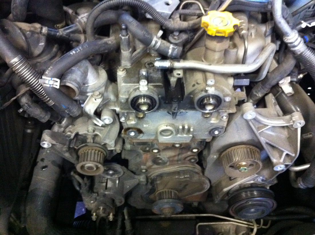
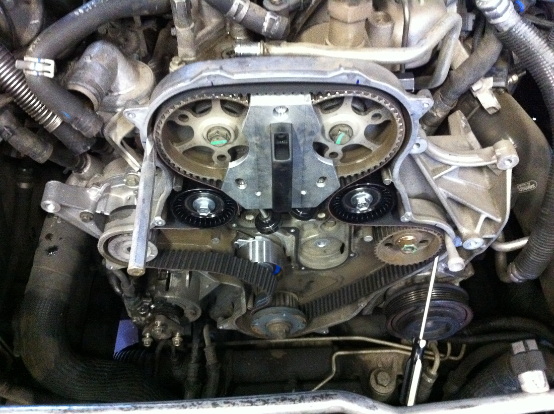
Timing belt procedure:
1. Remove front cover.
2. Install cam lock pins/crank lock pin/cam locking tool.
3. Add alignment marks on the crank, injection pump, and cam gears for safeties sake and to insure the CP3 injection pump stays timed correctly.
4. Loosen TB belt pulley tensioner bolt.
5. Use tensioner tool to back the tension off of the belt.
6. Remove Belt.
7: skip if not doing water pump
7a. Remove cam gears
Only do this with cam locking pins installed and gear holder in place. The torque required for the cam gear bolts can break the locking pins!)
7b. Remove rear cover.
7c. Remove viscous heater.
7d. Remove water pump front half.
7e. Install water pump front half.
7f. Install viscous heater.
7g. Install rear cover.
7h. Install cam gears
Only do this with the cam locking pins installed and gear holder in place. The torque required for the cam gear bolts can break the locking pins!
8. Install new belt.
9. Tension belt and lock tensioner.
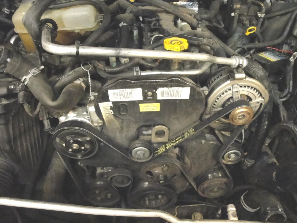
1. Remove front cover.
17x7mm hold the front cover on. Remove them and then the cover will just pull off. Set aside.

2. Install cam lock pins/crank lock pin/cam locking tool.
NOTE: If you are not doing the water pump the cam gear holder tool is sufficient to hold the gears in place, and the cam pins are really not needed in that case.
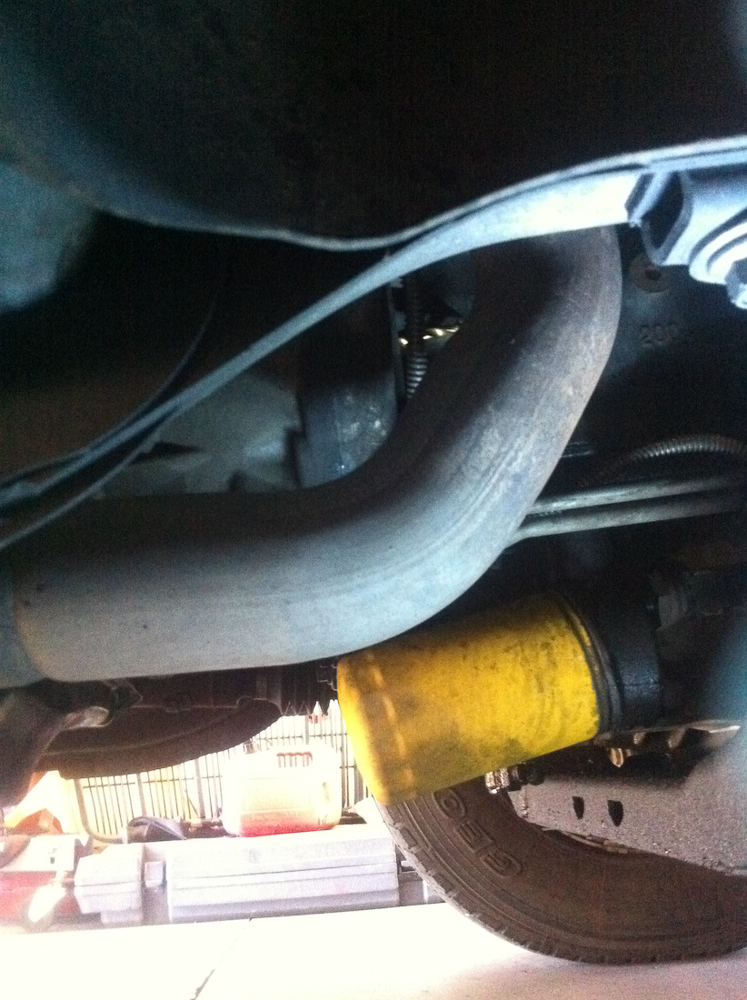
The cam lock pins are labeled with an "I" and an "E" for intake and exhaust respectively. They install at 90° aTDC, but they can also install at 270° aTDC. To install the intake pin you will need to remove the alternator. To install the exhaust locking pin it is helpful to remove the 10mm bolt holding a water hose in place to gain clearance. The plugs that need to be removed to install the locking pins are a 6mm hex. The crank locking pin installs into a small hole on the block above the oil filter. Generally the hole is dirty and rusty so the factory tool does not like to thread in. I recommend just using a similarly sized drill bit on the block/flywheel hole. Start by removing the plug for the intake, use something like a smaller screw driver to feel for the cam locking pin hole while you turn the crank, when you feel the hole try installing the locking pin, turn the crank back and forth until the locking pin installs easily. Then check and see with the drill bit if it can be inserted into the flywheel, if it bottoms out very shortly you are probably 180* degrees off(IE you are at 270° aTDC and need to be at 90° aTDC), remove the pin, turn 180 degrees and repeat. Once you get the flywheel pin/drill bit through install the other locking pins fully and put the gear locking tool in place.
This is the Intake cam locking tool: (Miller 1052)
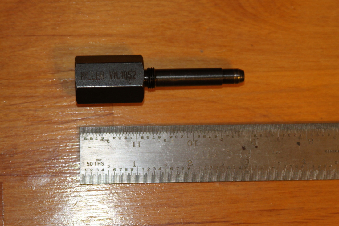
This is the Exhaust cam locking tool: (Miller 1052)
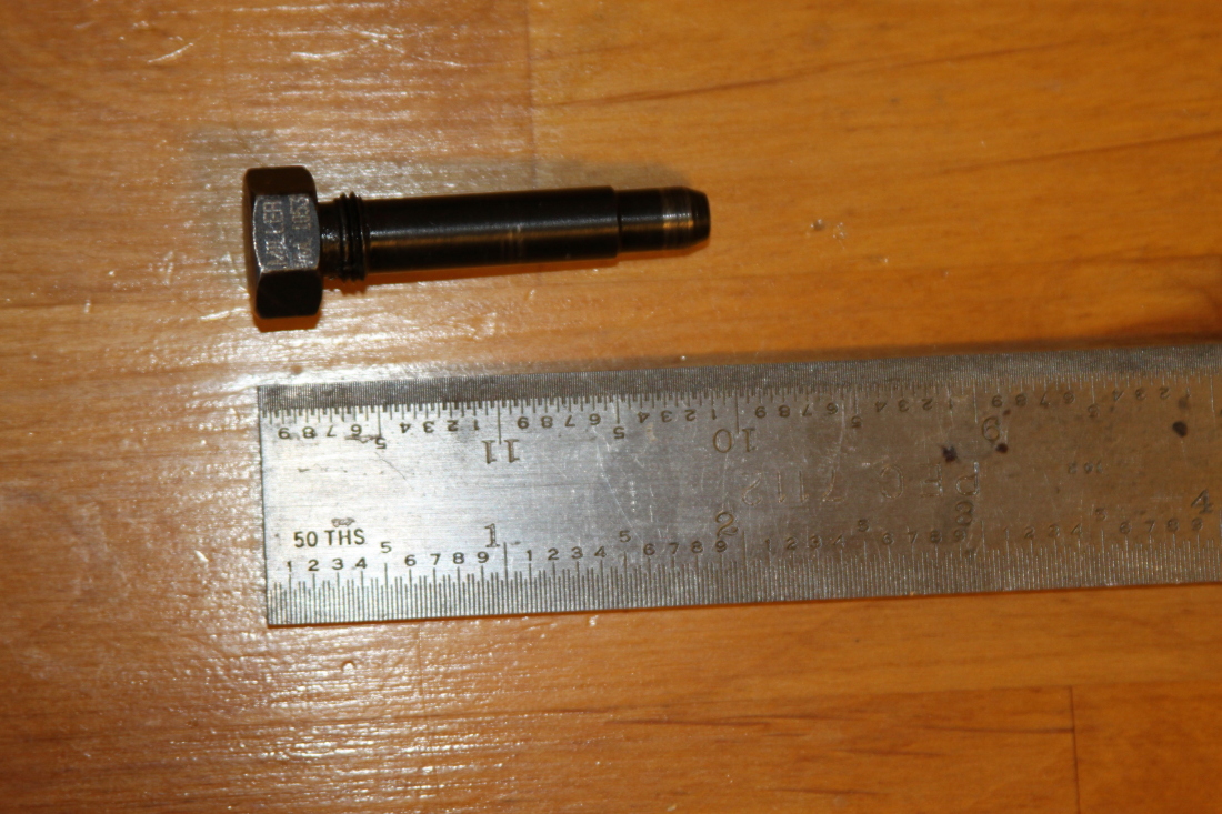
This is the crank locking tool: (Miller 1089)

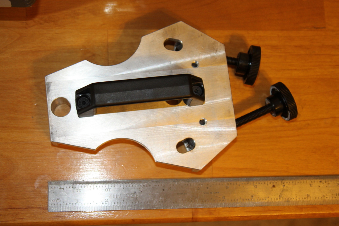
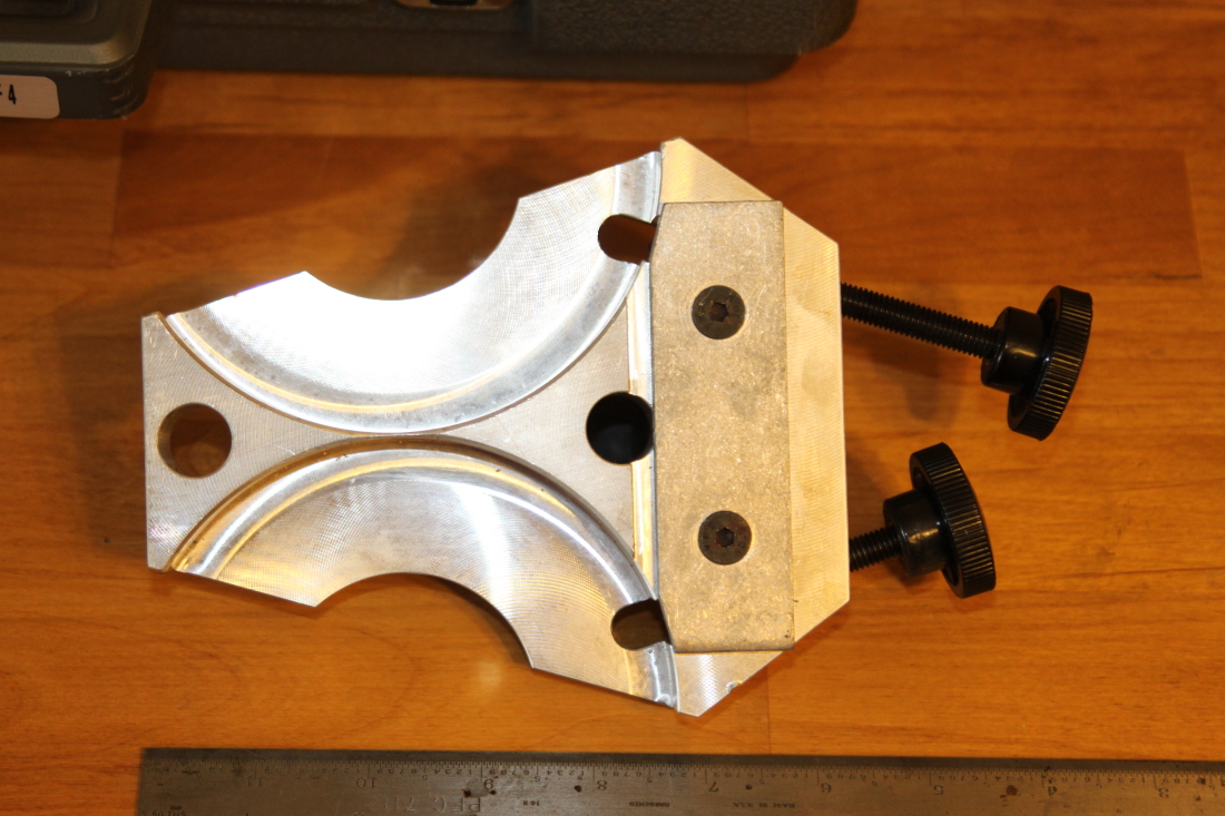
This is the cam gear locking tool: (Miller 1085)
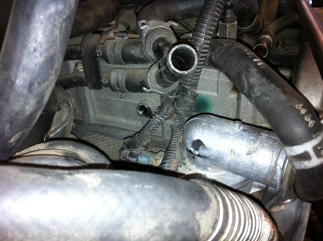
In the center of this image is where the 6mm plug is that needs to be removed to install the intake locking pin:

This is where the exhaust cam locking pin tool needs to be installed:
Here you can see the intake tool installed(and the rear cover off, but don't pull that cover yet!)
This is where the flywheel locking pin tool should be installed:
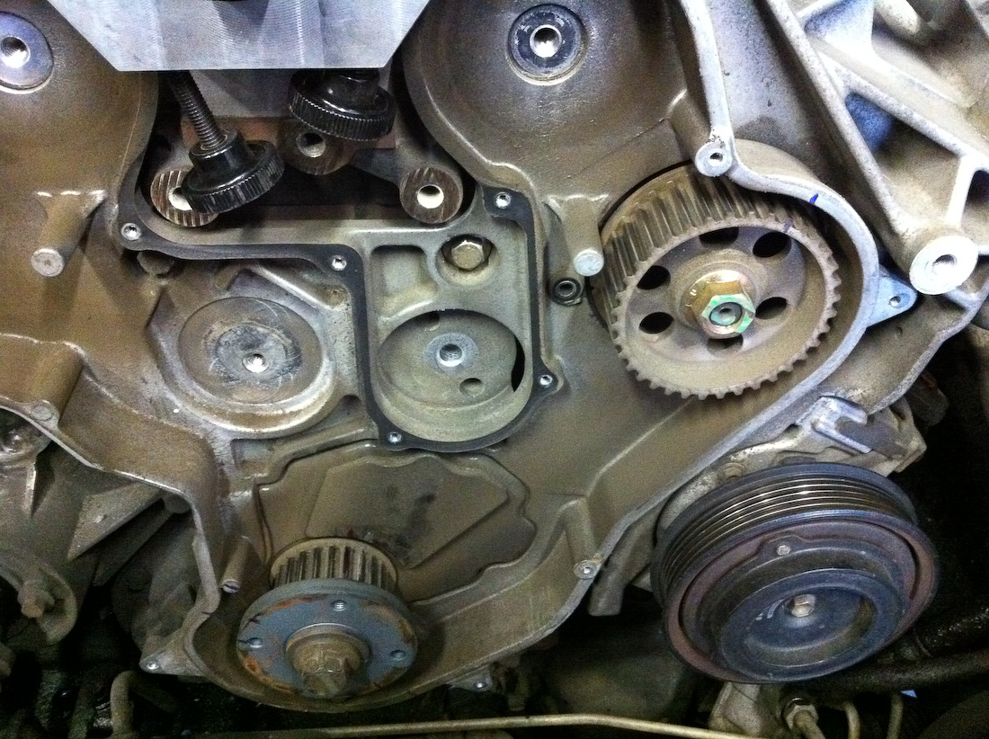
3. Add alignment marks
You should add alignment marks on the crank pulley, cam pulleys, and injection pump. No need to mark the water pump, it isn't timed at all.
Cam gear alignment marks:
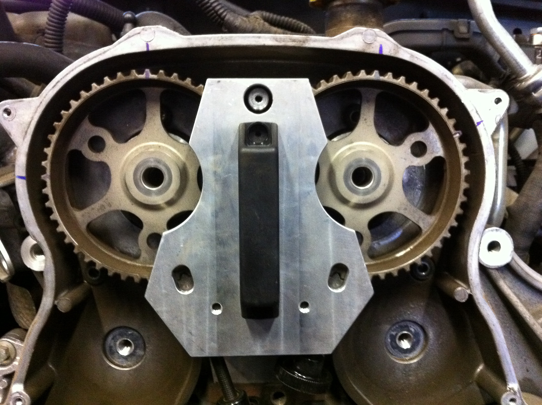
Injection pump, and crank alignment marks:
I generally put several marks on the crank, including the teeth, as safeties.
4. Loosen TB belt pulley tensioner bolt.
With everything marked, with the locking pins in place, and the cam gear tool in place, loosen the 10mm bolt on the timing belt tensioner, then use the tensioner tool to back the tension off the belt. If you were not at 90° aTDC then the crank might turn a little, don't worry, this is why you marked it. Just make sure your marks line up when you get the belt on. After loosening the tensioner, slide the belt off, remove the tensioner.
Tensioner:
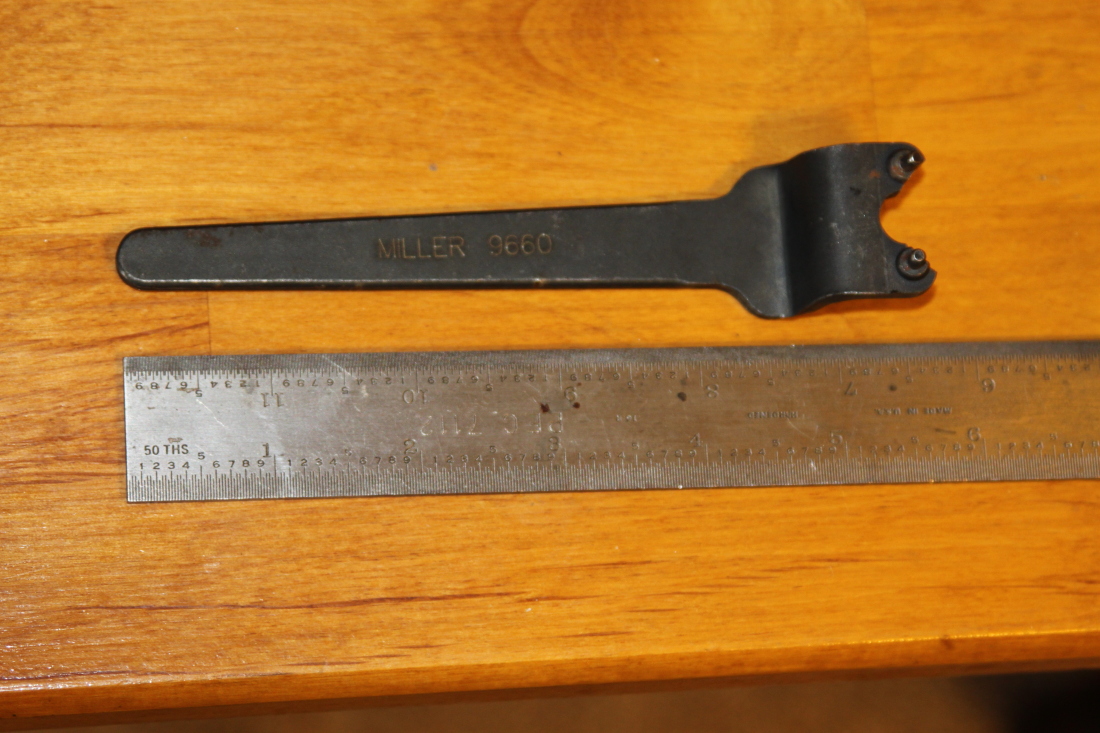
This is the tool for adjusting the TB tensioner: (miller 9660)
7a. Remove cam gears
With all the pins in place and the cam gear locking tool in place(make sure the knobs are screwed in tight) remove the bolts that hold the cam gears on, 17mm. With the bolts removed the cam gears will just pull off. Set aside.
Only do this with cam locking pins installed and gear holder in place. The torque required for the cam gear bolts can break the locking pins!)
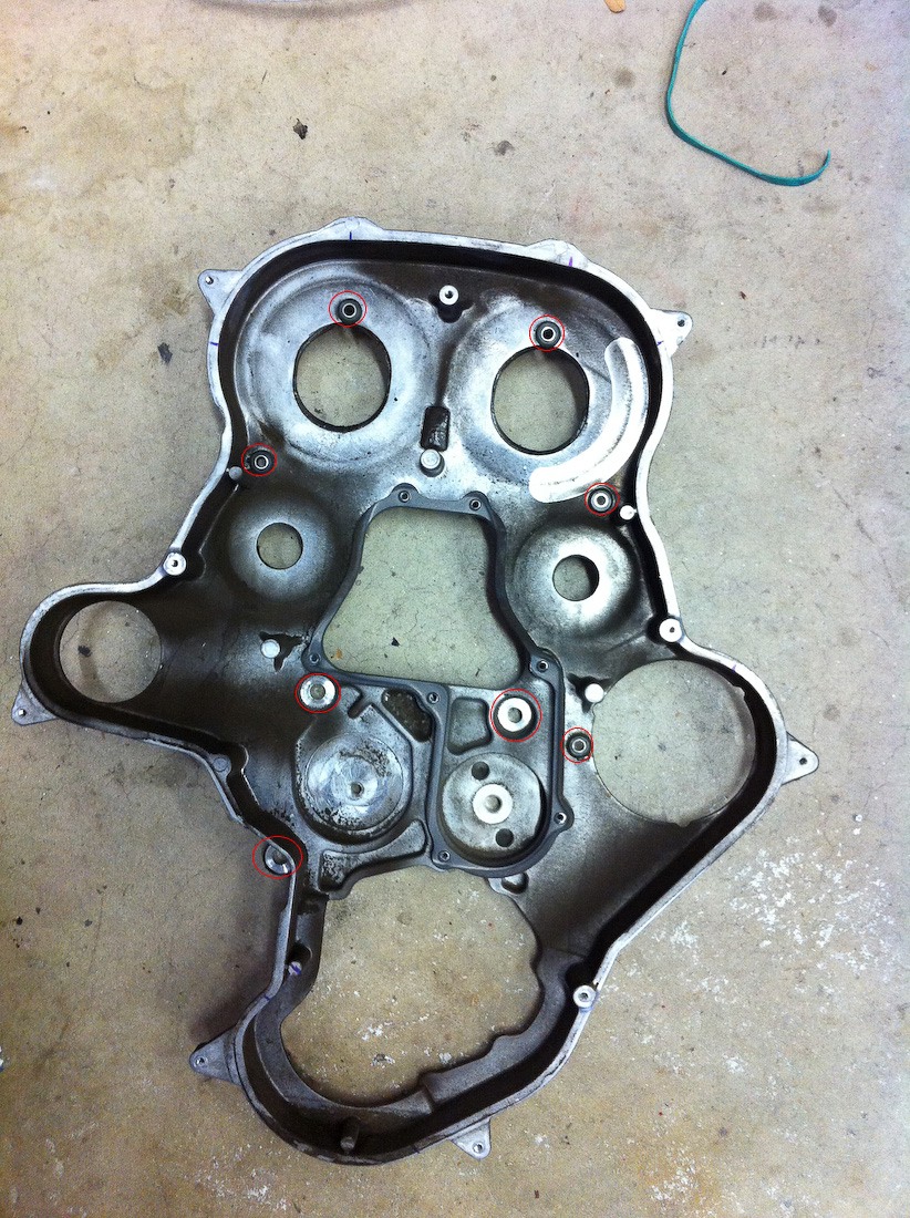
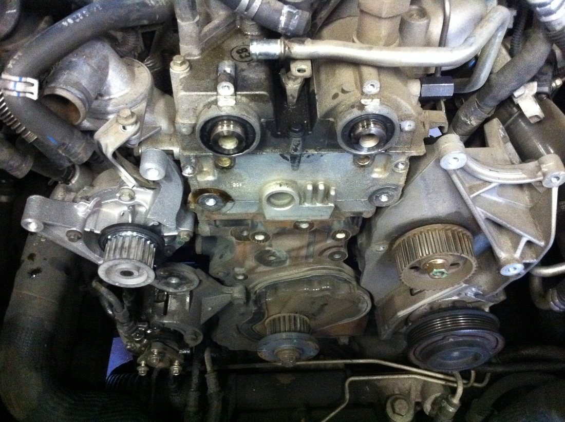
7b. Remove rear cover.
Removing the timing belt idlers, the timing belt idlers have reverse threads! Turn them clockwise to loosen. The rear cover has 6 small bolts and 3 larger ones noted in these two pictures(one is located behind the cover and also holds down a water pipe).

7c. Remove viscous heater.
Two bolts, a couple of heater hoses, and an electric plug. No photo yet.
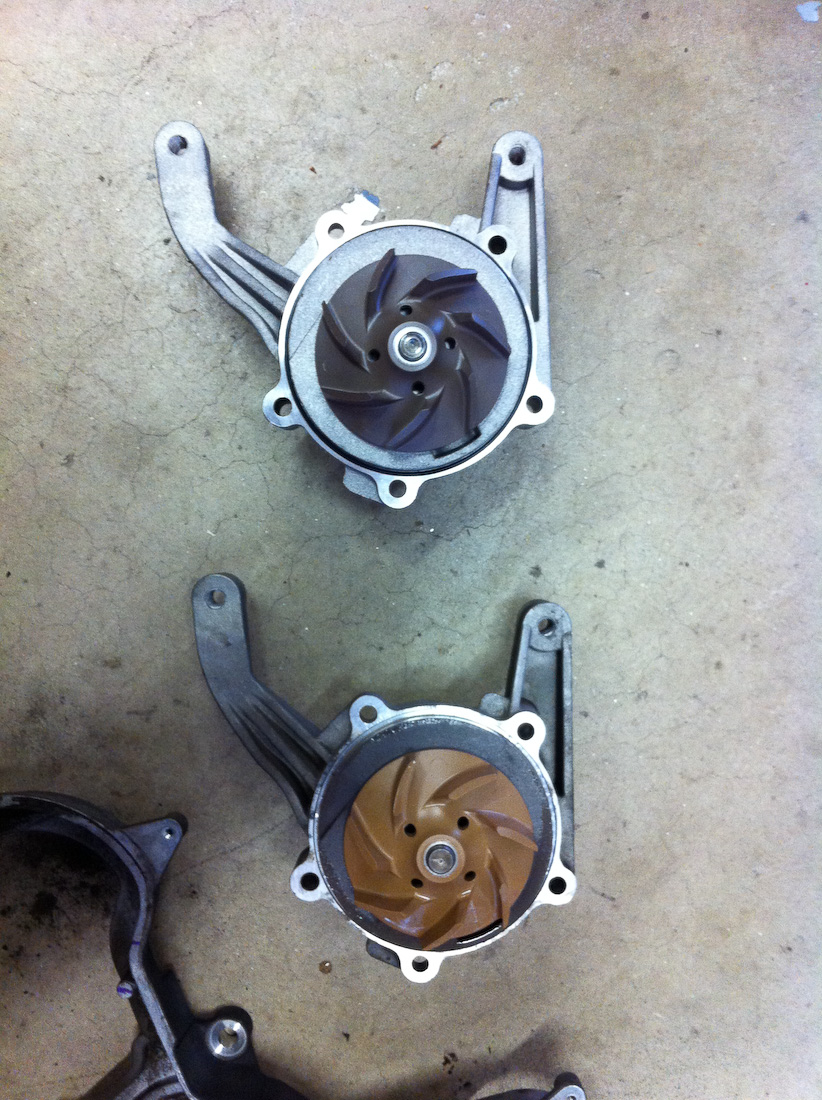
7d. Remove water pump front half.
5 bolts, be mindful that there are different length bolts, but its obvious where they goto and come from.
Water pump front half removed(not old o-ring still in place, remove and then clean surface):
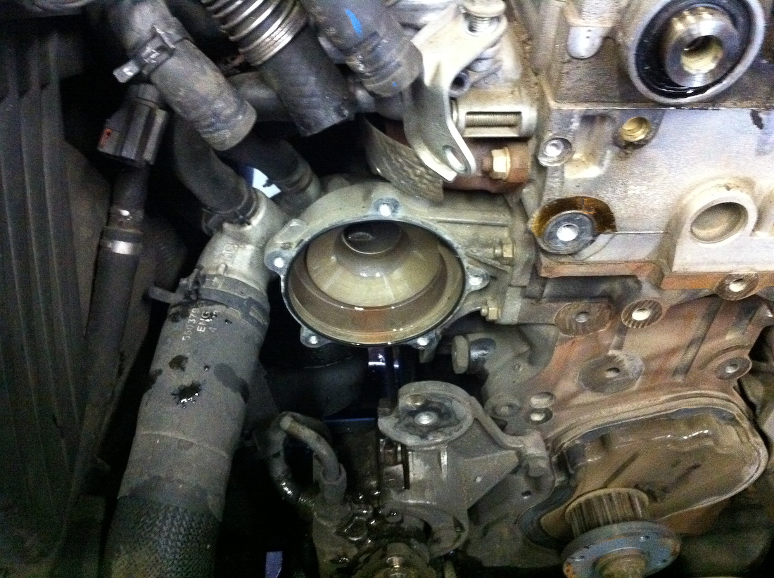
Go ahead and remove the new front half. Make sure the oring is properly seated in the groove on the new front half. Make sure the old water pump oring is removed from the rear half.
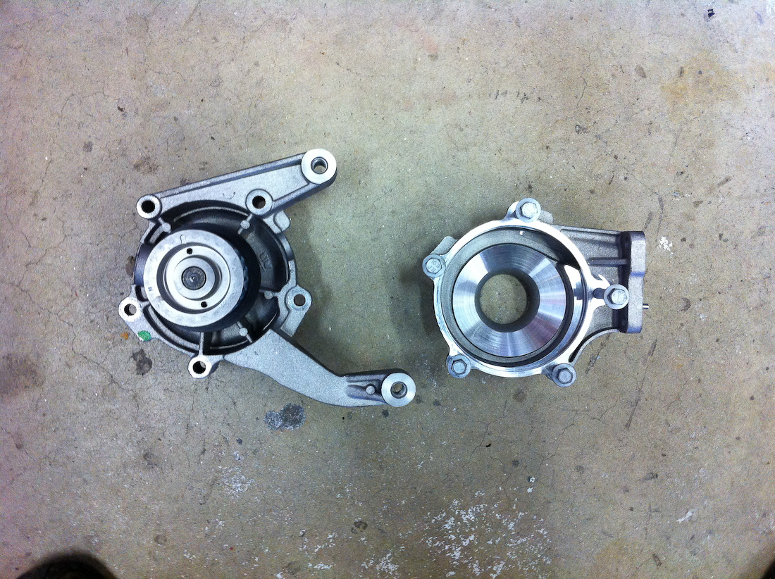
New top, old bottom:
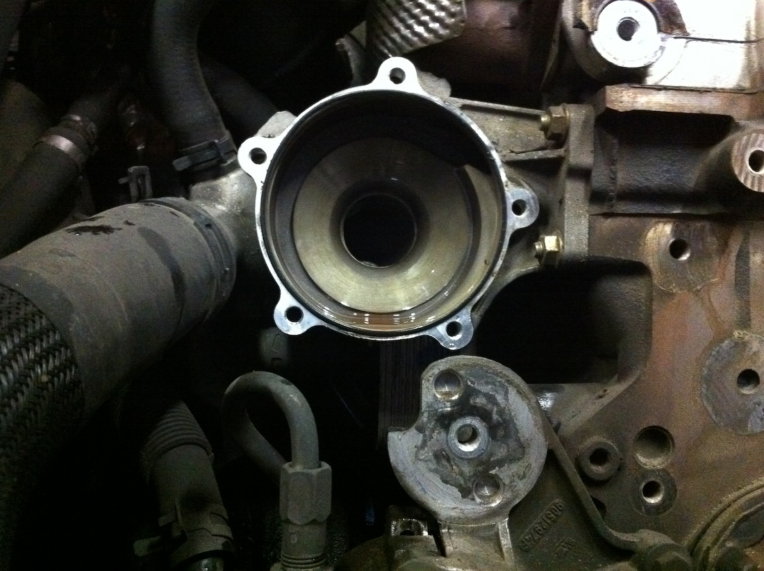
7e. Install water pump front half.
New pump with oring installed(make sure the new Oring is properly seated, and then lightly lube it with grease, make sure the old seating surface is clean)
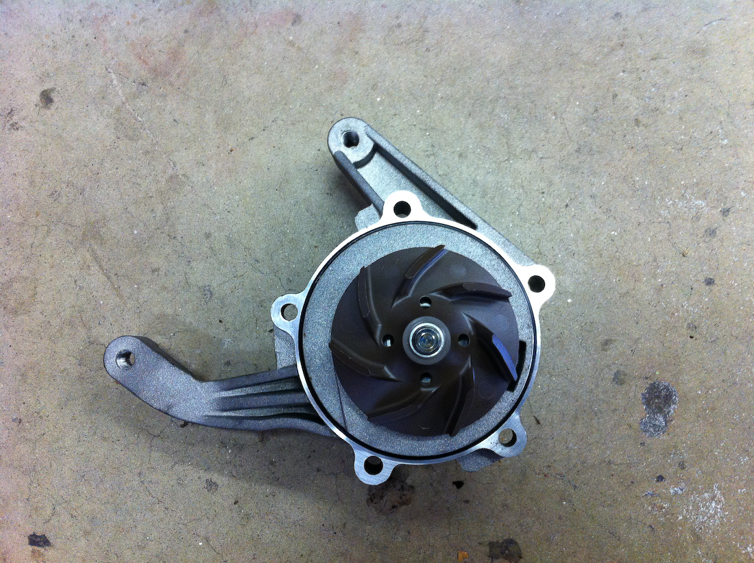
New front on old rear:
(Much much less work this way than trying to use the new rear)
7f. Install viscous heater.
7g. Install rear cover.
7h. Install cam gears
Only do this with the cam locking pins installed and gear holder in place. The torque required for the cam gear bolts can break the locking pins!
8. Install new belt.
Reinstall idlers, reinstall belt tensioner(but don't tighten it yet.) For the Belt generally I start at the cam gears, and then work my way around down past the IP and then down to the crank. Make sure that there is not any slack between the two cam gears, if you can move the belt up and down any it means you have an extra tooth between the two gears. Install the belt so there is no slack between the gears. It is often best to start at the top and slide the belt onto the gears keeping it tight, don't try and get it over one gear first and then the second gear next. Slide it over both at the same time. After this is done and to keep the belt from popping off I generally use something as a wedge to keep the belt from popping off of the cam gears. Screwdrivers are fine, just don't shove in a huge one and damage the belt. The nozzle from an RTV tube worked very nicely, I'm sure you have something around you can use.
The Belt should be tight like this between the gears, if there is any play it has an extra tooth between the gears:

Now quite often you will get into a case where you have something that looks like this:
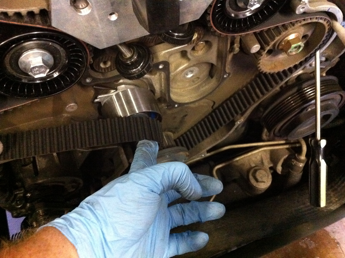
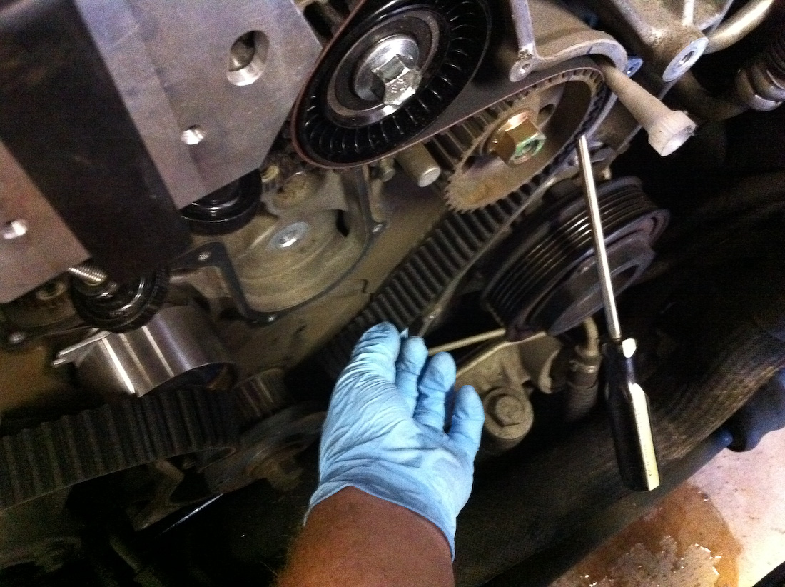
What happens is that you do not have enough slack to slide over the tensioner, and you have too much slack between the crank and the injection pump, yet you cannot get the belt to catch a tooth further over than it has on the crank. What you want to do is turn the crank CCW, and then get the belt to catch onto a tooth on the crank, then hold the belt onto the crank, and turn it back CW. If you do it right you will have a tight belt between the injection pump and the crank, and then barely enough slack to get the belt over the tensioner, make sure your crank timing marks still lineup. if you are off by a tooth it will be obvious, repeat the procedure until you have no slack between the IP and the crank, and your crank is correctly aligned.
Check out this video on youtube to see what I mean:
VIDEO LINK HERE
9. Tension belt and lock tensioner.
Use the tensioner tool to tension the belt where the tensioner mark aligns, then screw in the 10mm bolt tight. Double check that all the timing marks lineup, remove all locking pins, cam gear holder, and then turn it over by hand. Verify that all the marks still lineup after a couple of rotations. If they do, do a test startup. If everything sounds good put it back together.
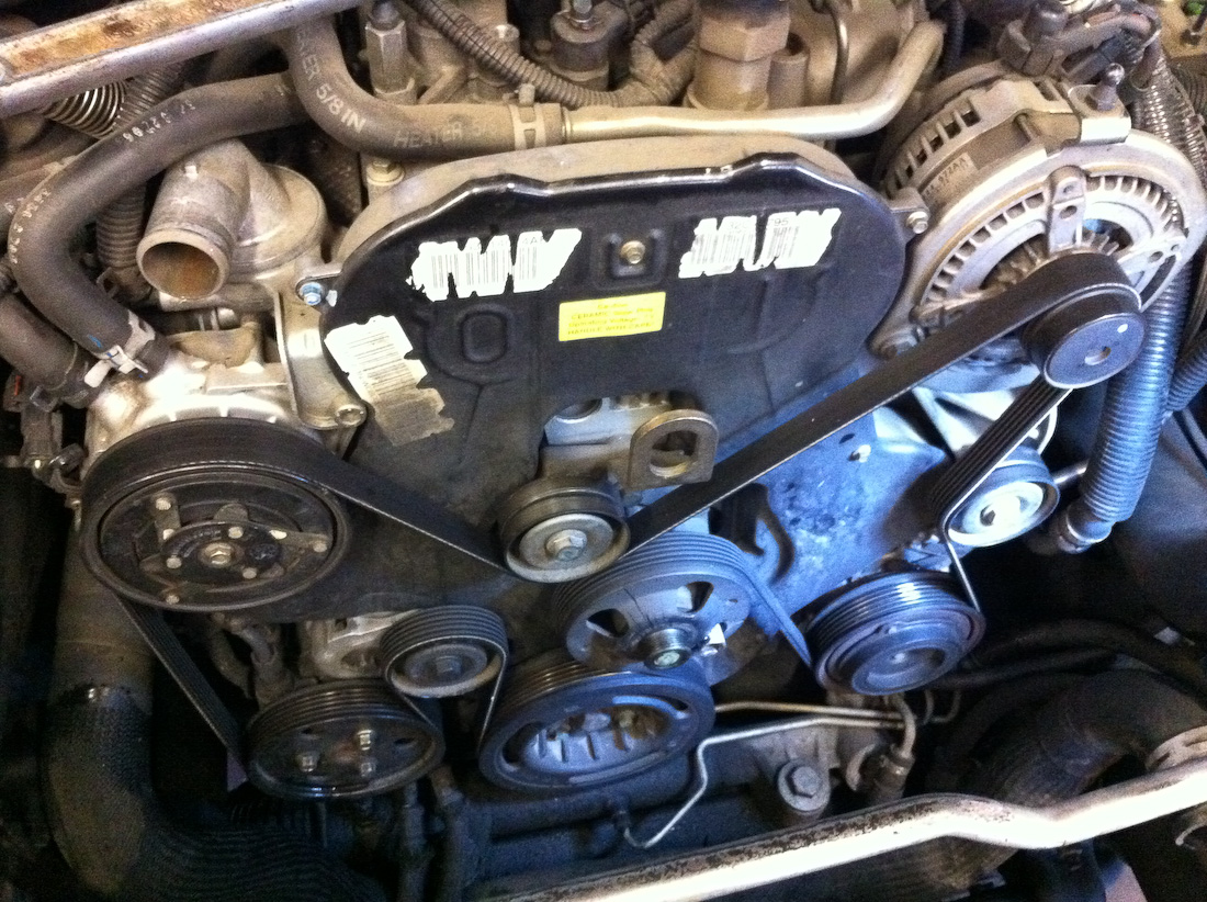
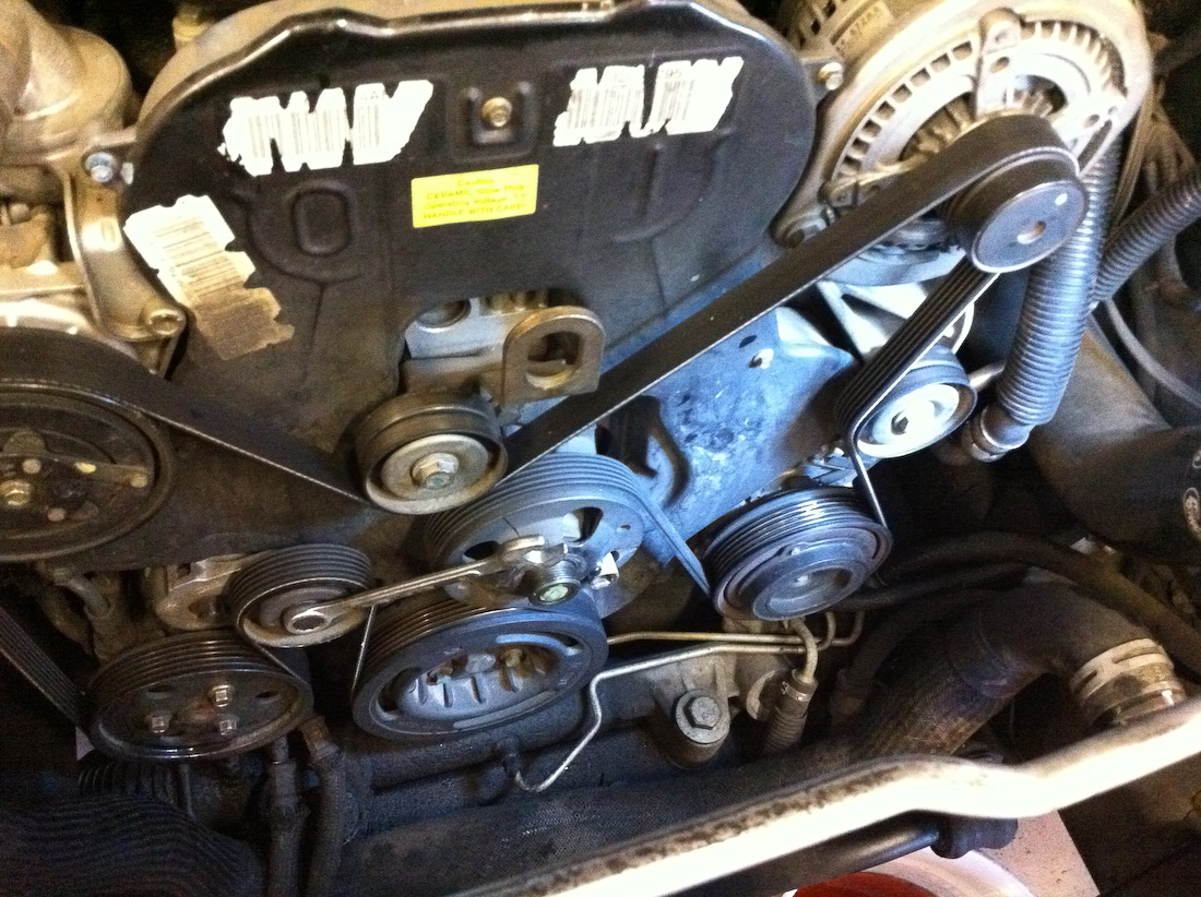
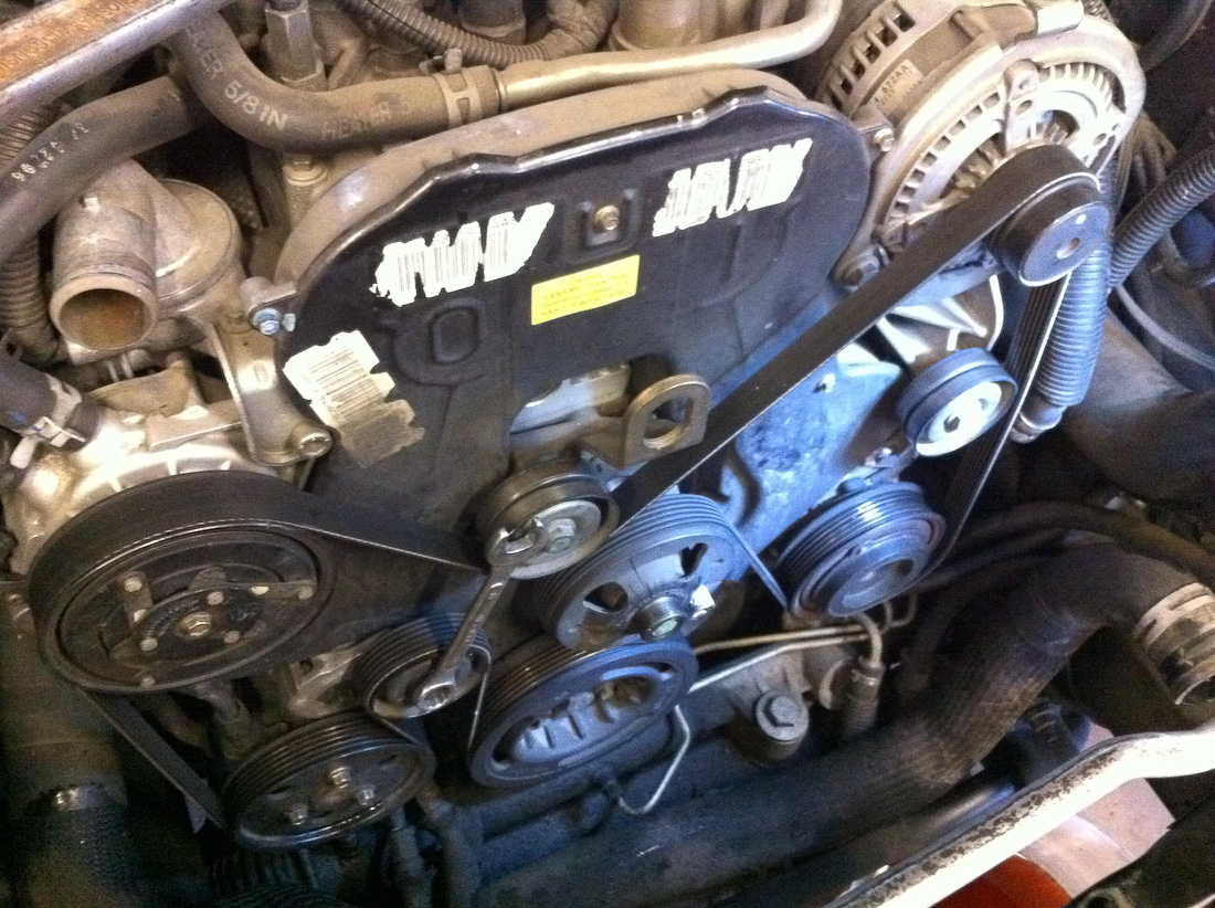
This is the serpentine belt routing in case you're like me and forgot the instant you took it off:
Lets take a look at a used Timing Belt with 111k on it:
Surface wear:
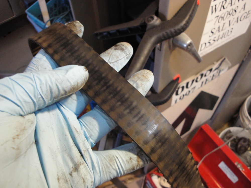
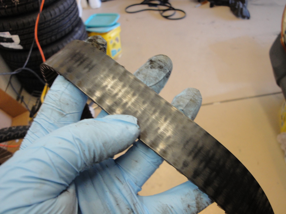
Underside looks better, but still is covered by the fine red dust that comes off the belt as is bends and flexes.

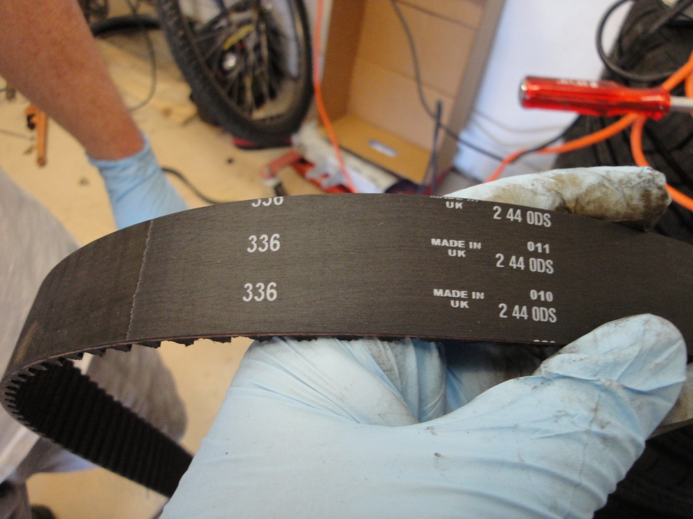
This is the new belt in comparison to the old, much less wear and it looks much better.
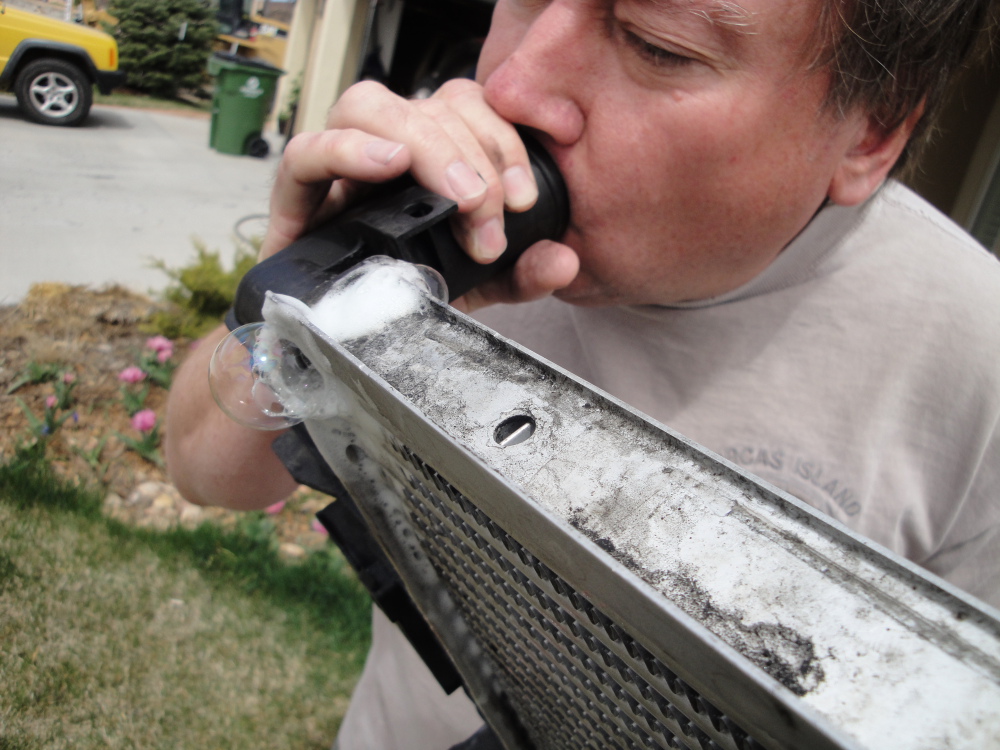
Pressure testing the intercooler:
With one hand over the outlet and my mouth firmly sealed to the inlet(No Jokes Please) I blew hard and could feel and hear some leakage, after making sure my mouth and hand seals where good I uses the old soap suds trick to find a location that was leaking.
So we got a little JB weld, mixed it up, and made it flow into the area in question(the top most tube on the inlet/hot side of the intercooler).
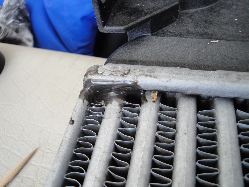
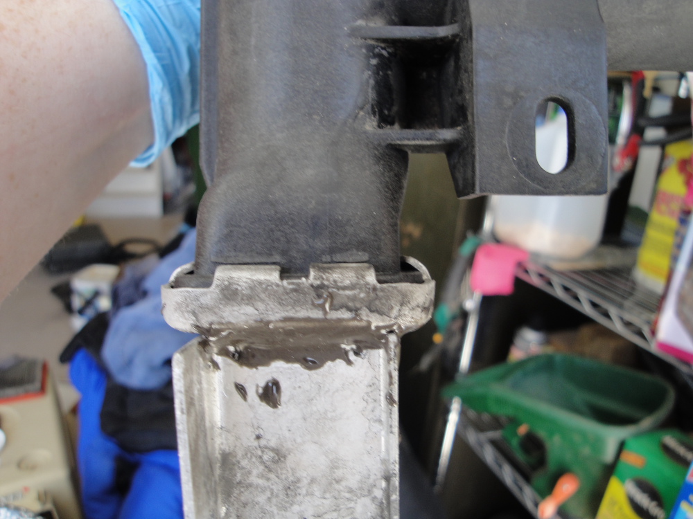

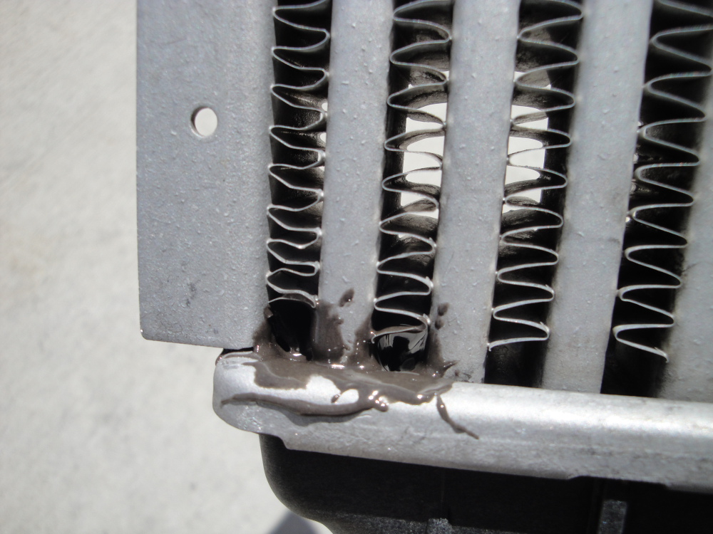
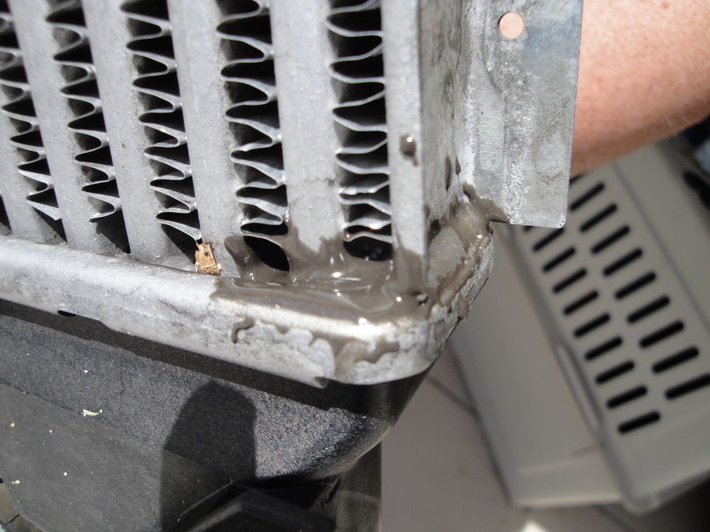
Problem solved! No more leaks from that location. During tear down there was a good buildup of oil on the IC near the leak, most likely oil from the intake pathway being blow out the small leak(right by the inlet) and covering the IC with a nasty oil buildup. If you see the same thing happening then you may be having a small IC leak like I was.
Do not loose these:
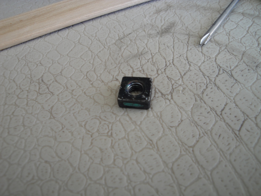
There are a bunch of these located all in the radiator and the IC. They are small threaded inserts that simply slide in to a plastic holder on the radiator or IC and let other things like the fan shroud and AC condenser bolt to them. I lost several and had to find some nuts that would work. I didn't even realize these could come out until I went to reassemble everything and found out I was missing them!
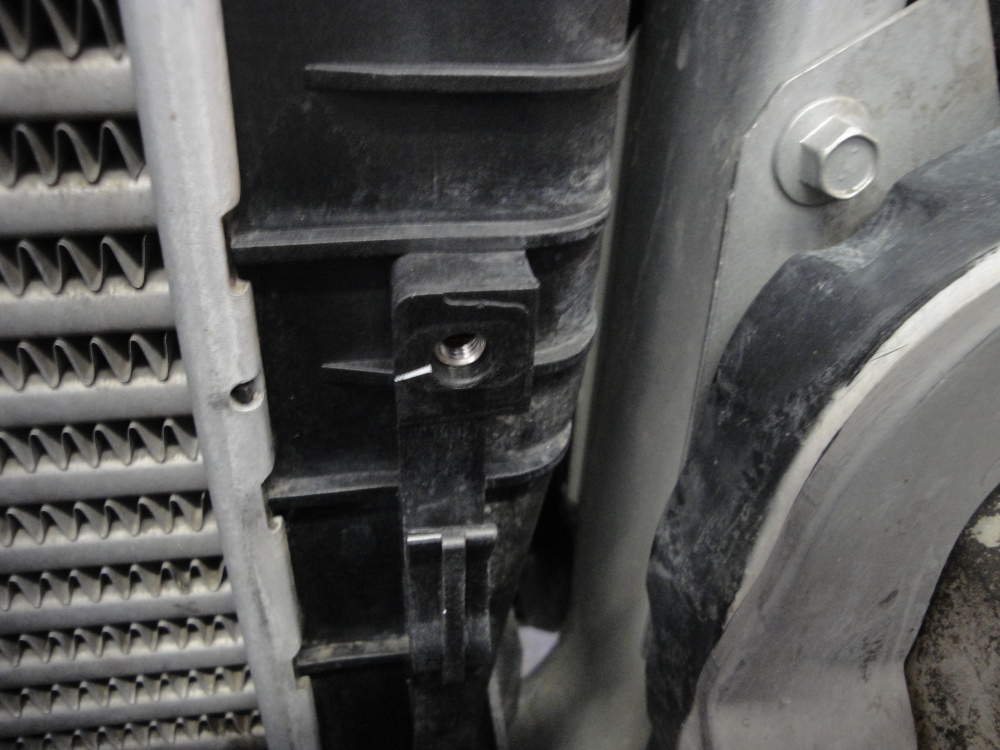
Example of one not missing:
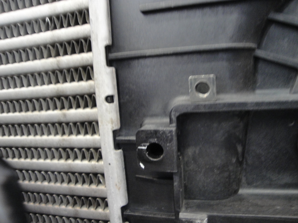
And one thats missing:
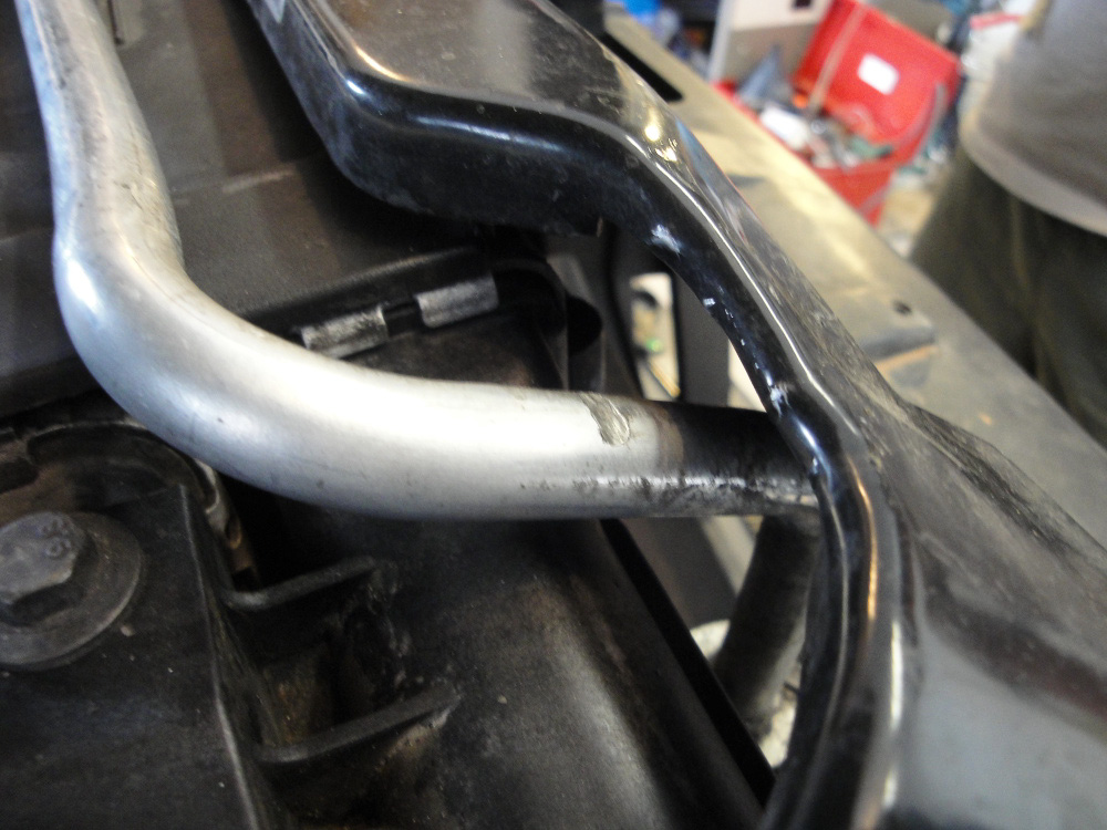
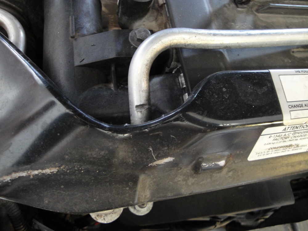
This was something I noted upon reinstall of every, the AC line had been hitting the upper radiator support, I bent the lip of the radiator support a bit and also bent the line down a bit, lots of clearance now!

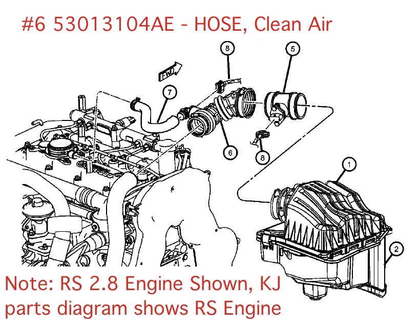
This is the turbo inlet hose. When I was putting everything back together I found out that the lower part where it clamps to the turbo inlet had degraded and ripped apart. I suspect it had been this way a while and only now I had discovered it. It appears that this will be a 100% failure item on most CRDs, mine has been running the EHM and ORM for the past 60-70k miles(since about 40k-50k on the odometer) and I still had this failure. The stock CCV system will increase this failure rate, yet another reason to run the EHM and ORM.
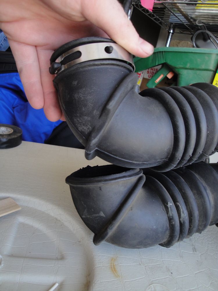
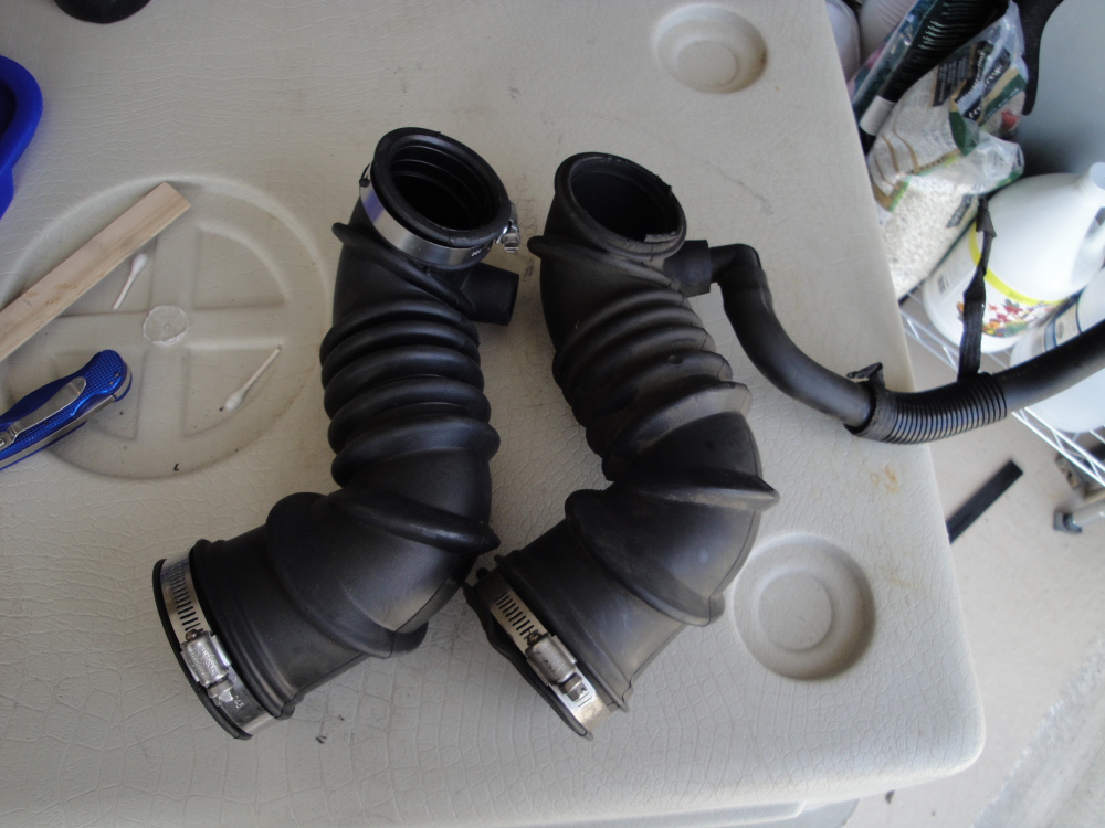
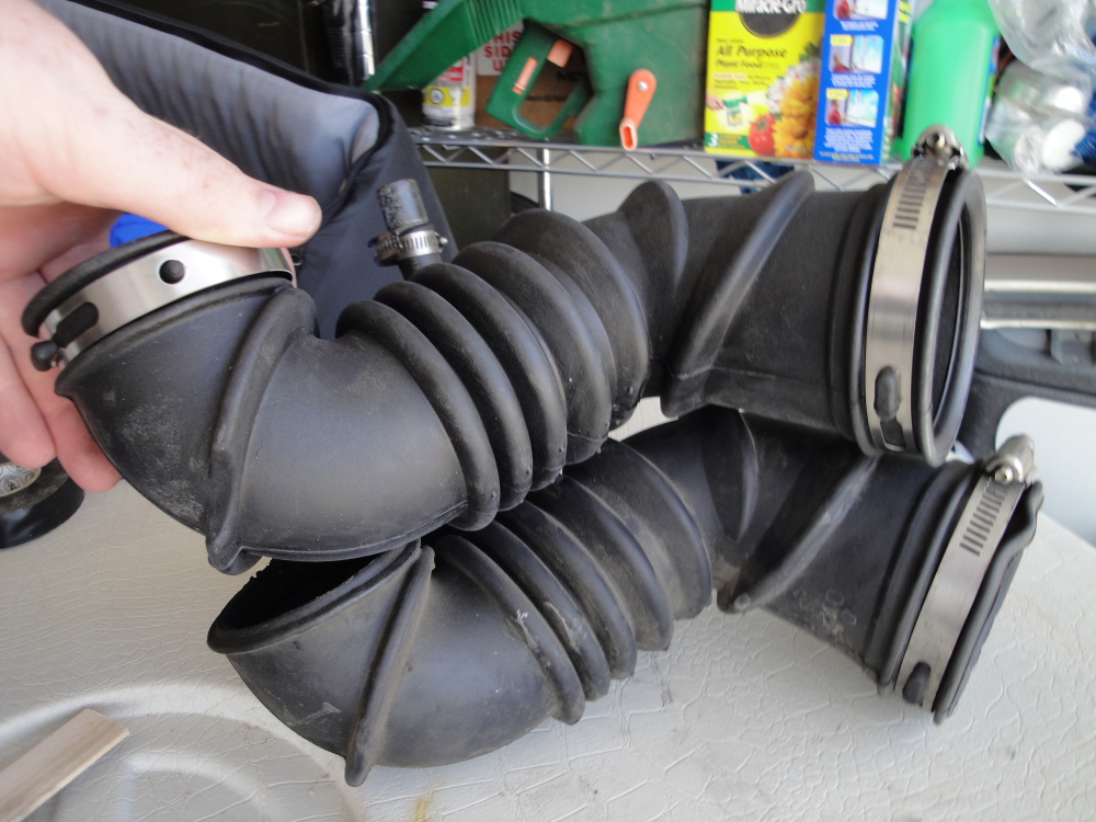
The Part number for the new part is 53013104AE - Hose, Clean Air: